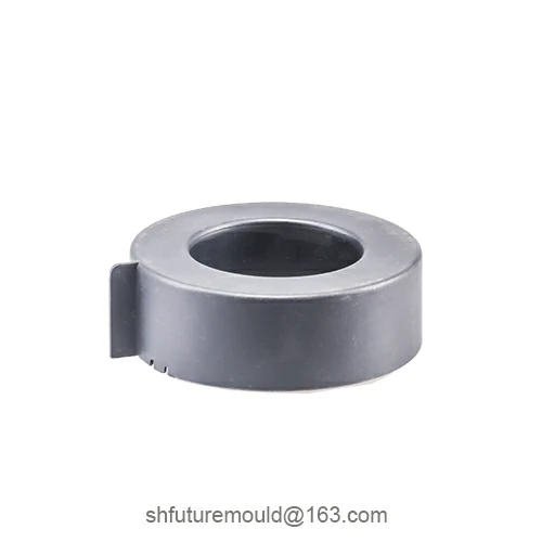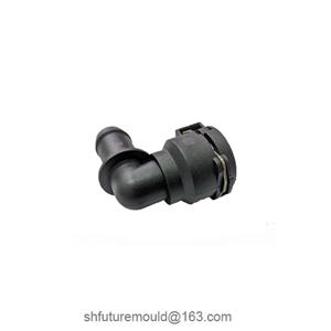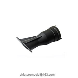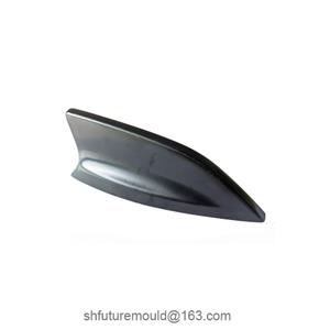
Design of Venting Grooves in Injection Molds
During injection molding, incomplete gas expulsion can lead to defects such as short shots, burn marks, and gas traps. As a critical component of mold venting design, scientifically optimized venting grooves are essential for ensuring product quality and production efficiency.
Rational Layout of Venting Grooves
1. Key Placement
Venting grooves should be positioned at critical locations such as:
The junction of the cavity and gate
Complex structural features
Tightly enclosed areas
This ensures air escapes along the shortest path.
2. Avoiding Melt Leakage
Vent placement must balance sealing requirements. Grooves should expel gas efficiently without allowing melt leakage during filling.
Optimizing Venting Groove Dimensions and Geometry
1. Dimensional Design
Undersized grooves impede gas escape, while oversized grooves risk flash or surface defects.
Dimensions (depth, width, length) must be calculated based on material viscosity, flow rate, and temperature, followed by empirical validation.
2. Geometry Optimization
Common groove shapes include:
Rectangular
Semicircular
Angled designs
Depth typically ranges from 0.02–0.04 mm, ensuring effective gas channels without disrupting melt flow.
Maintaining Cavity Seal Integrity
1. Balancing Venting and Filling
Grooves must expel gas while preserving cavity sealing. Techniques include:
Micro-grooves for controlled venting
Baffle plates to balance gas escape and melt flow
2. Preventing Melt Intrusion
Narrow groove openings or adjustable valves prevent high-pressure melt intrusion into vents.
Material and Manufacturing Considerations
1. Material Compatibility
Mold material properties (thermal expansion, conductivity) and machining methods (precision milling, EDM) directly affect vent performance.
2. Machining Precision
Tight tolerance control (e.g., ±0.005 mm) is critical for micro-grooves.
Post-machining inspections (e.g., surface roughness measurement) ensure design compliance.
Mold Flow Analysis and Validation
1. Simulation Software
Mold flow simulation identifies:
Gas traps
Weak venting zones
Guiding groove placement and dimension optimization during design.
2. Trial Molding Adjustments
Simulations provide preliminary guidelines, but actual trial runs reveal surface/internal defects.
Iteratively adjust groove quantity, position, and size based on feedback.